Served as Team captain of Manipal University's Formula Student team - Formula Manipal from November 2017 to March 2019, during which I led the team in national and international events. Worked as E-Powertrain/Electronics Engineer from December 2015 to October 2017.
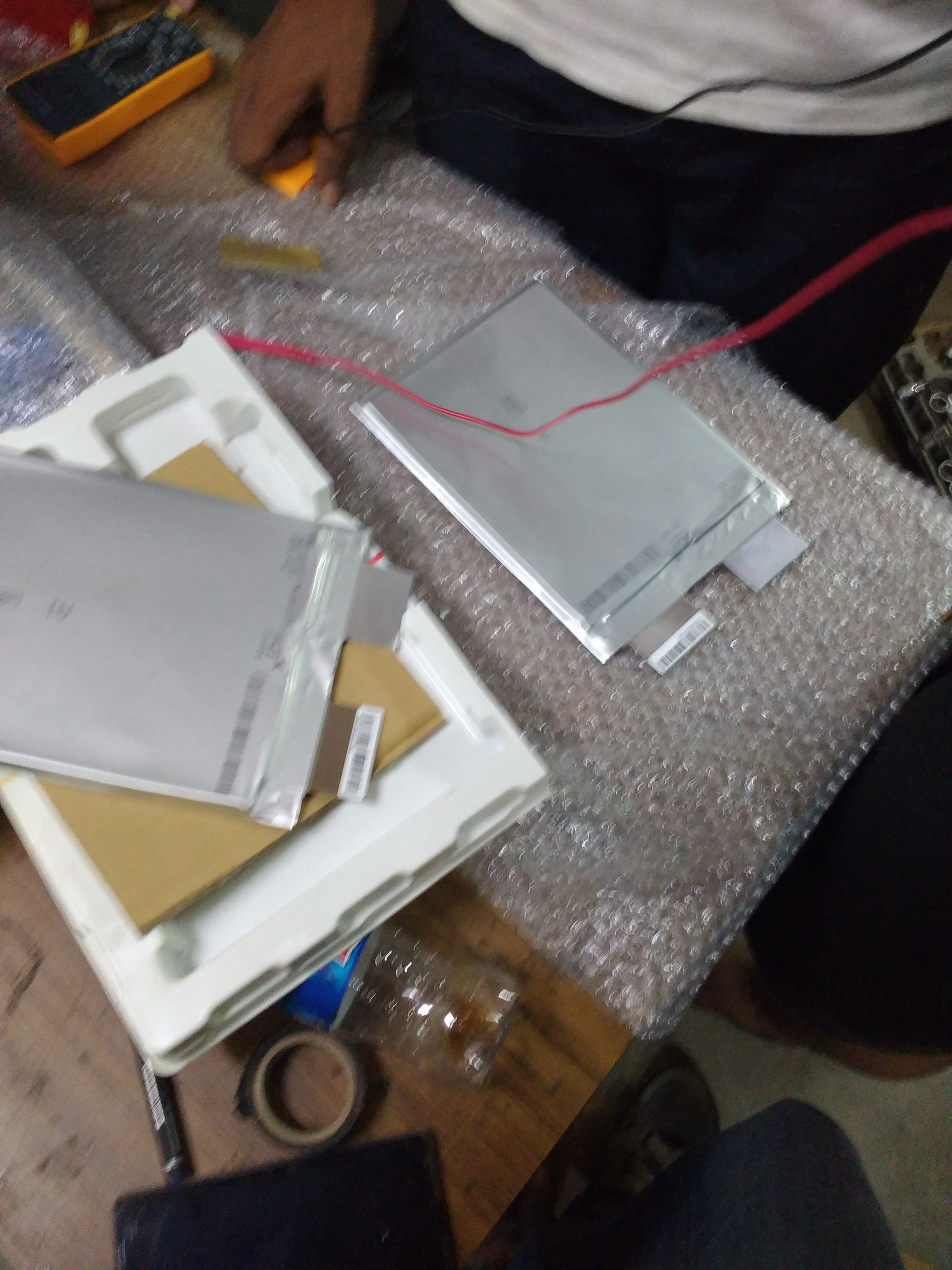
As a part of the team working on our first electric vehicle, I worked on developing energy storage technology for the racecar.
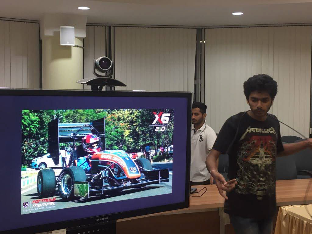
Co-ordinating rules quiz preparations as Team Captain
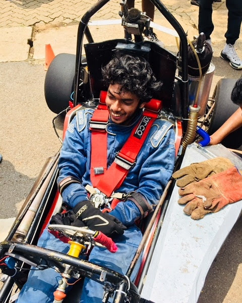
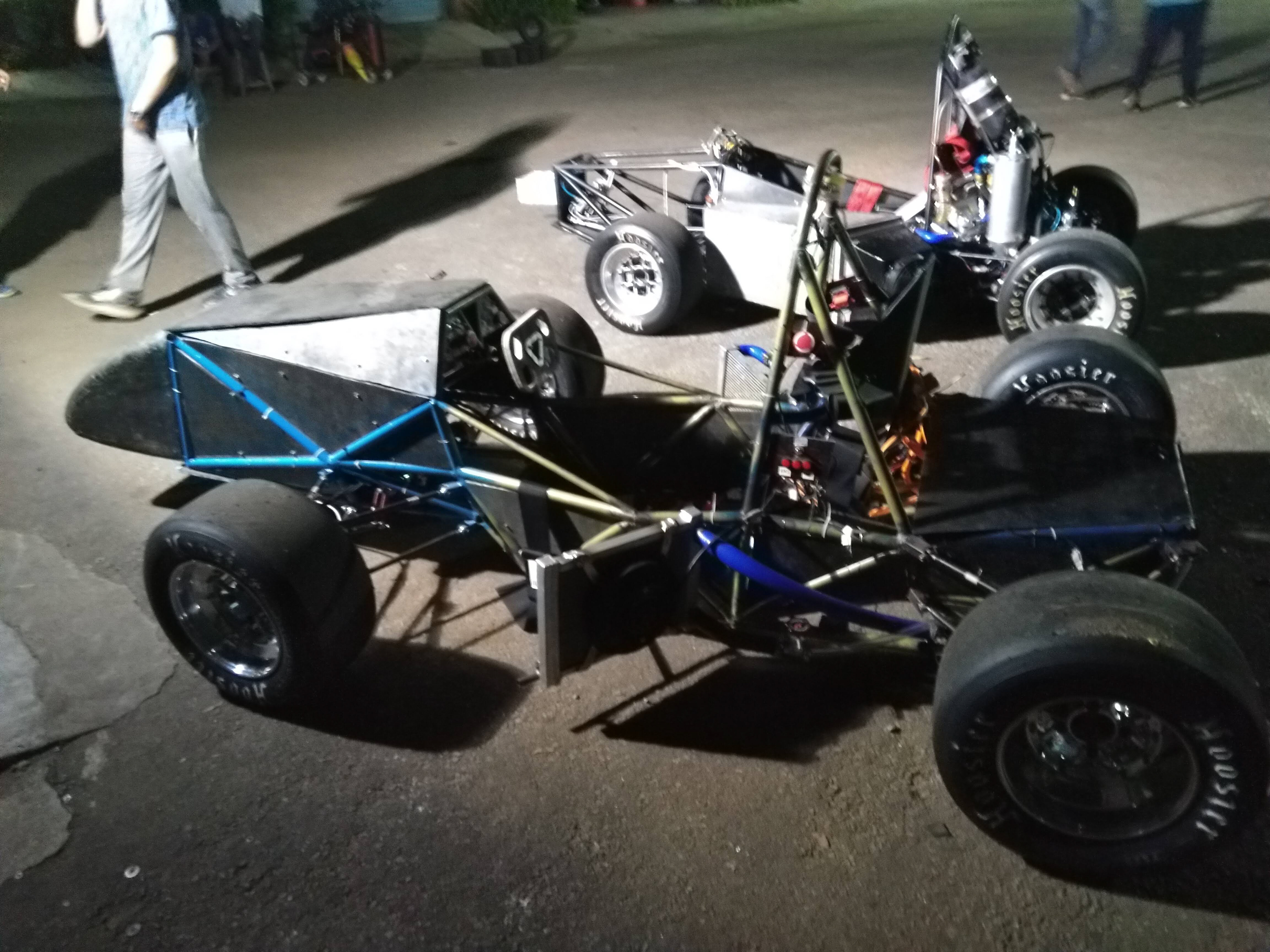
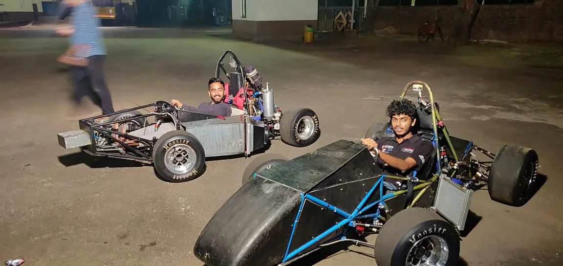
Testing the car
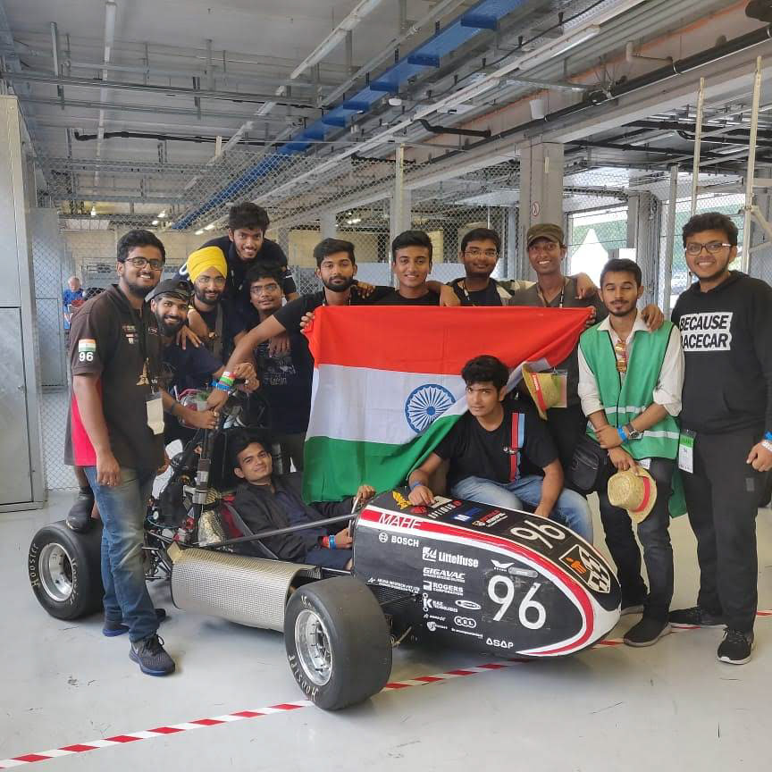
The class of 2018, representing the team at FS Austria
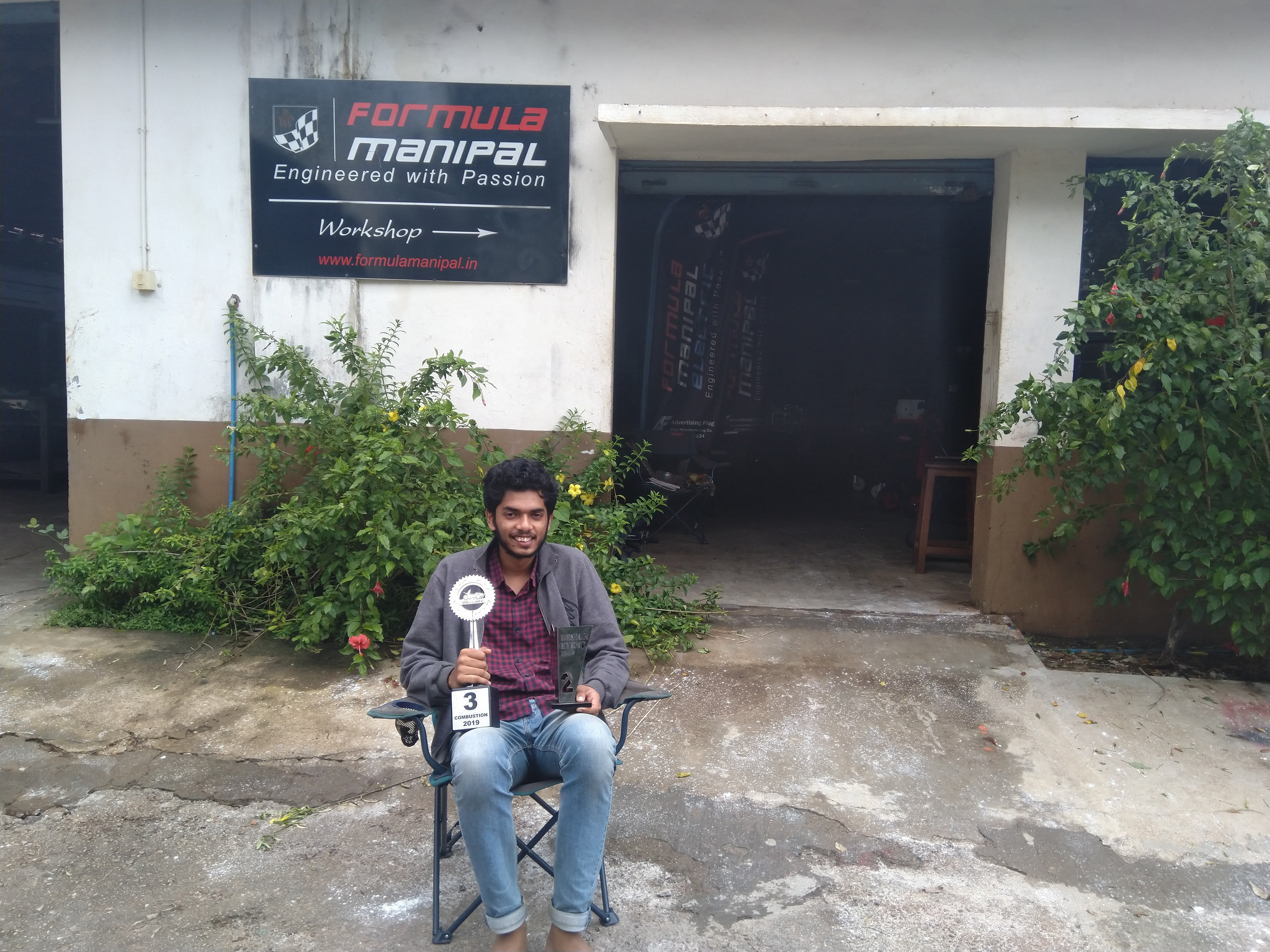
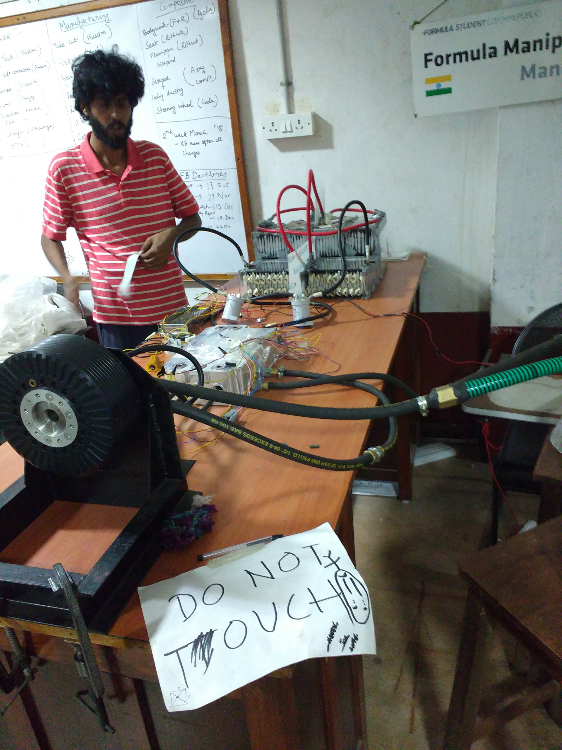
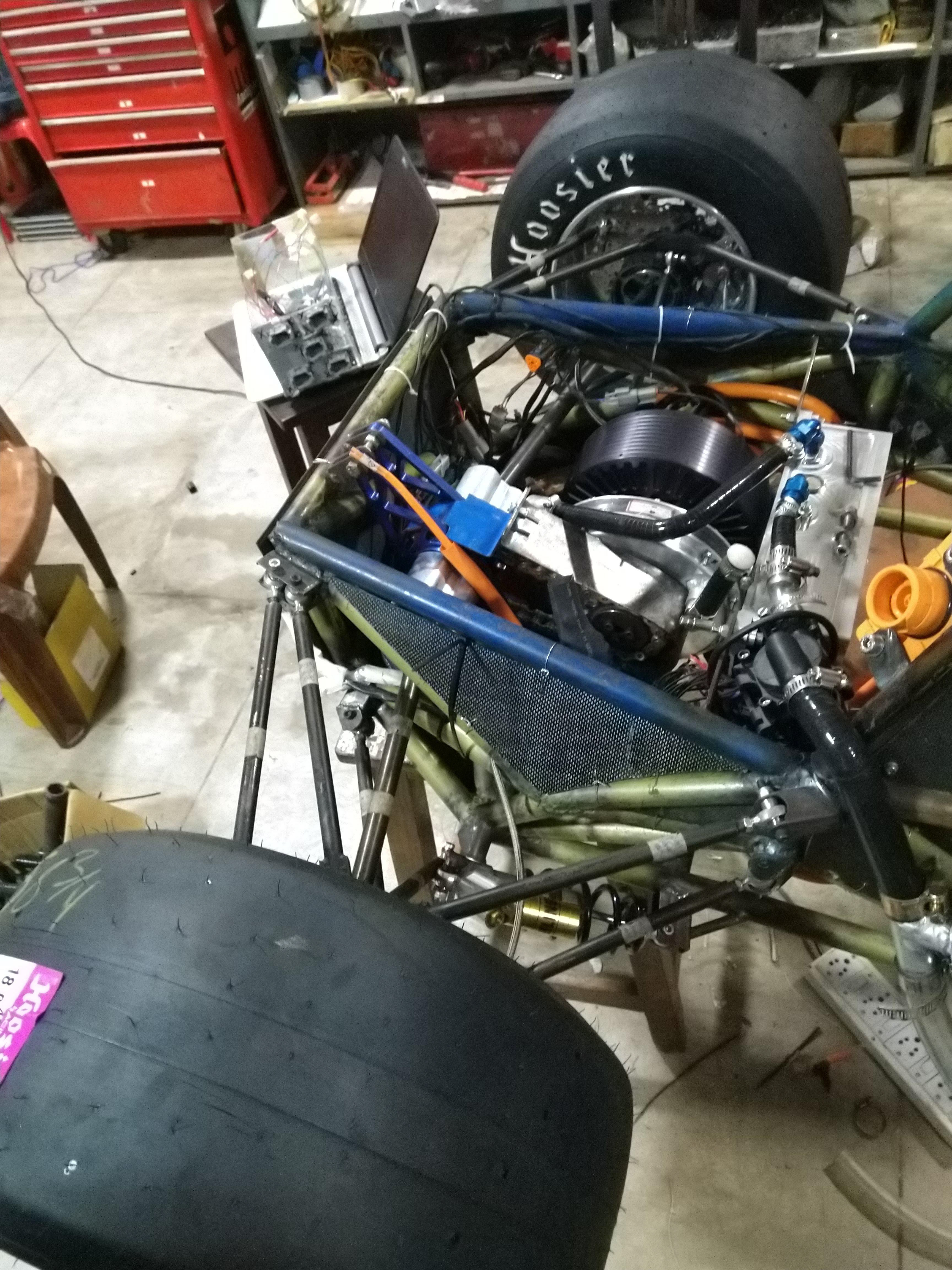
The workshop
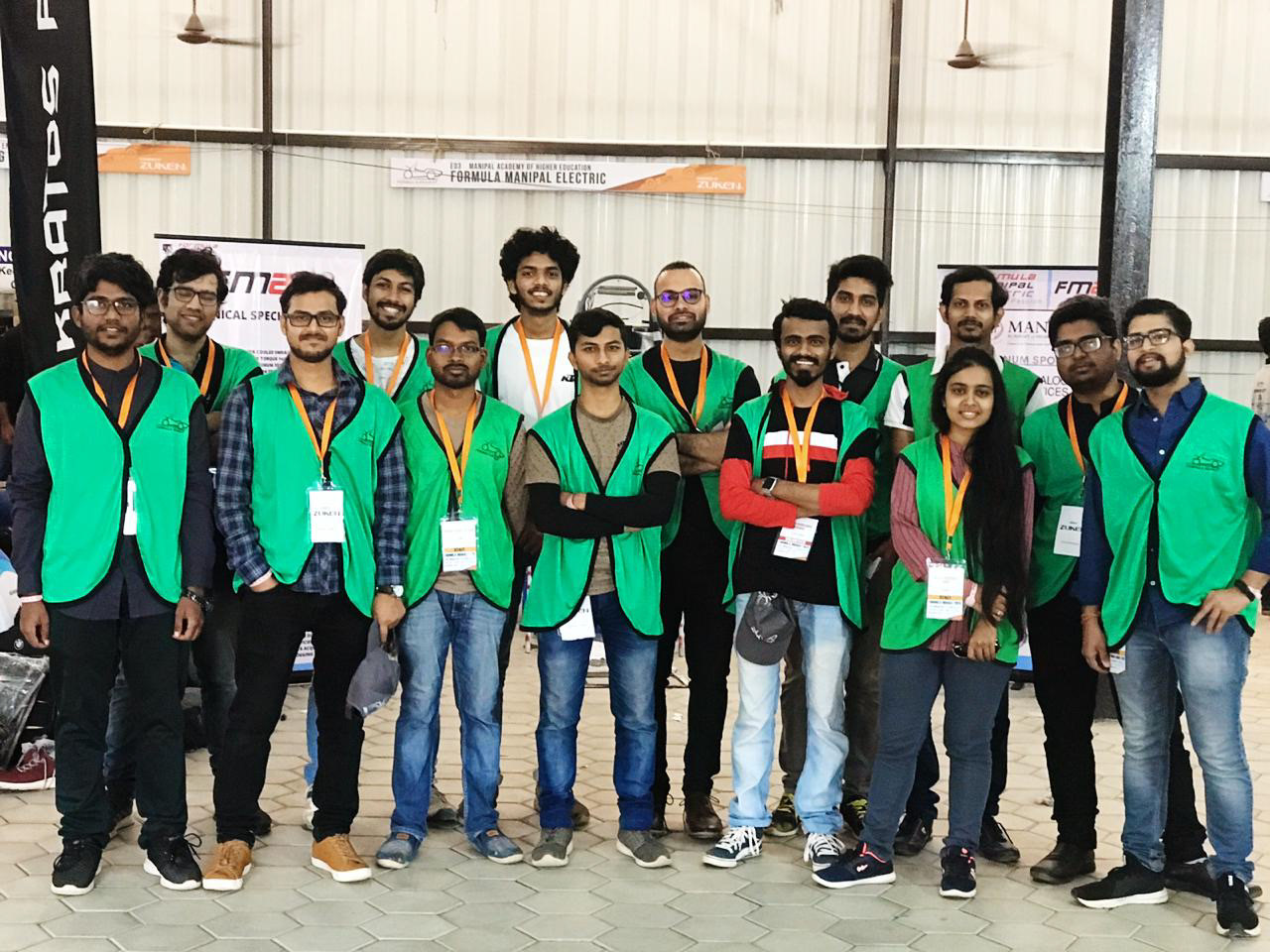
Working as a tech volunteer at Formula Bharat 2020
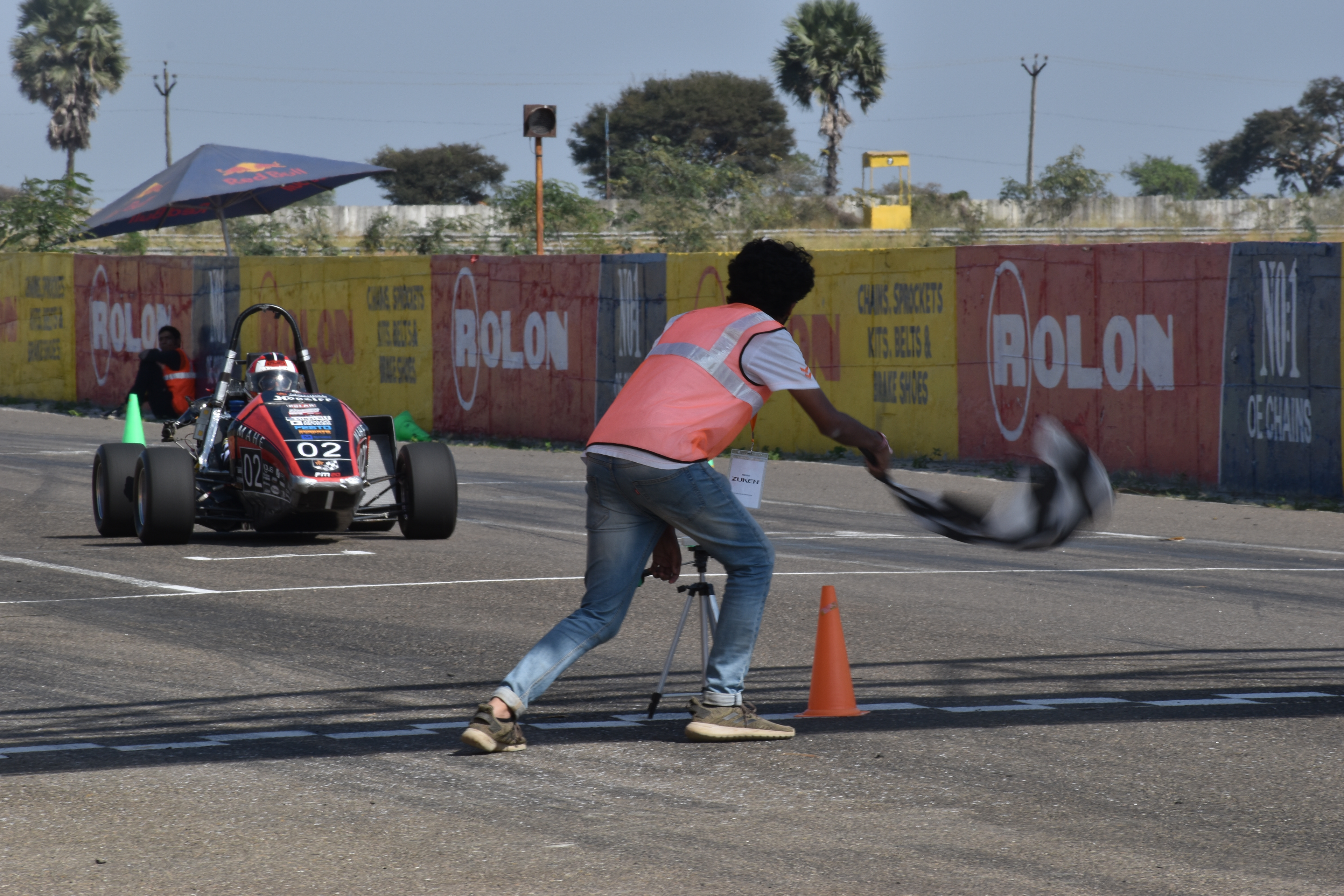
Checkered flagging my team's car at Formula Bharat 2020
Goal
To design a battery pack with the following considerations:
•Minimizing volume and mass
•Safety
•Reliability
•Safety
•Reliability
Design Process
Modelling for Estimating Required Energy
A MATLAB model was made to estimate the energy used by the motor over one endurance run, with wheel torque and rpm values given as input.
Modelling done with Karan Kumar, Priyaj Mehta
Cell Chemistry Selection
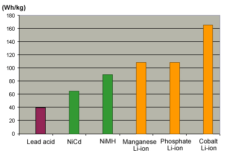
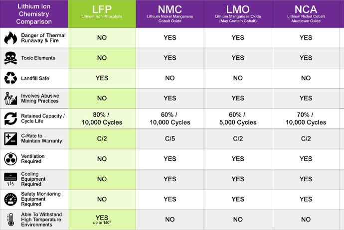
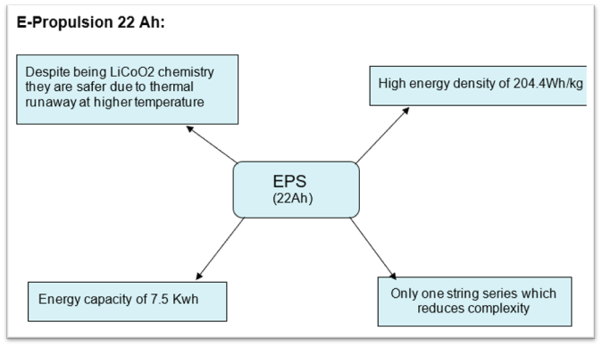
Cell chemistries were then compared based on energy density and inherent safety of the chemistry.
Cell Selection
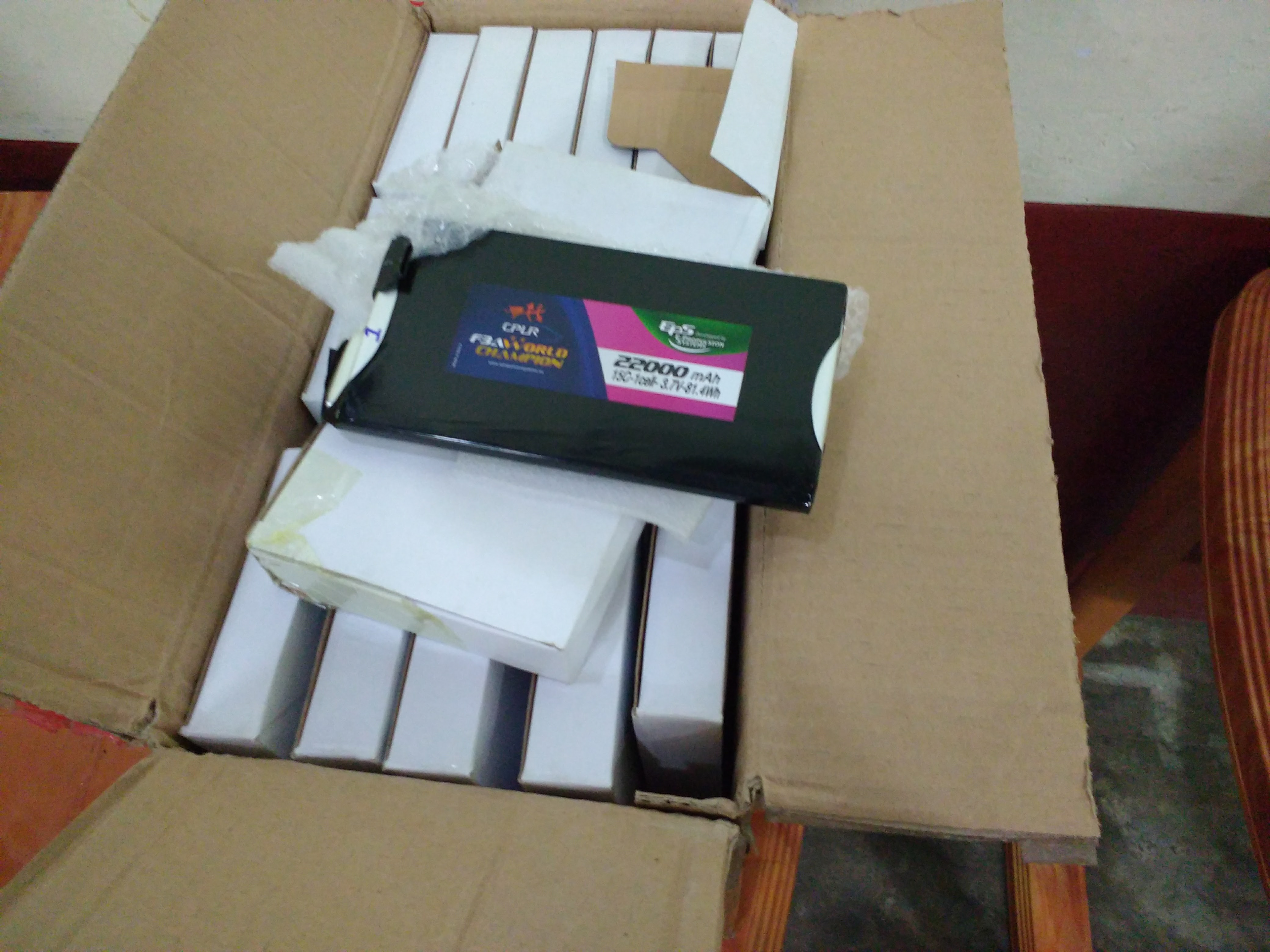
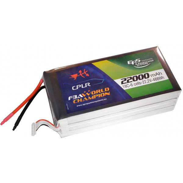
After comparing various brands of cells and capacities offered, EPS 22Ah cells in an 84 series string was the decided configuration.
Container Design Iteration 1
Iterations were made on how to package the 84 cells safely and in the least volume.
Shortcomings of the design:
•Poor packing efficiency in the car.
•Uneven cooling due to horizontal sweep of forced convection on the top layer.
CAD created with Karan Kumar, Priyaj Mehta
Container Design Iteration 2
Advantages over previous design:
•Increased packing efficiency in car.
•Extra box in front for electrical components like fuses, PCB’s, AIR etc.
Shortcomings of the design:
•Orientation of cells led to complex and long high current wiring inside the accumulator
CAD created with Karan Kumar, Priyaj Mehta
Final Design
Location of accumulator:
The accumulator was chosen to be just behind the driver seat to achieve a good packaging efficiency and less yaw inertia.
The accumulator was chosen to be just behind the driver seat to achieve a good packaging efficiency and less yaw inertia.
Accessibility:
The accumulator will be retracted from the bottom part of the chassis for easy removal for charging or maintenance purpose.
The accumulator will be retracted from the bottom part of the chassis for easy removal for charging or maintenance purpose.
Mounting:
The accumulator will be mounted to chassis using square tubes welded to its base plate which will be bolted to brackets on the chassis
The accumulator will be mounted to chassis using square tubes welded to its base plate which will be bolted to brackets on the chassis
CAD created with Karan Kumar, Priyaj Mehta, Harshal Gupta
Cell Stack Assembly
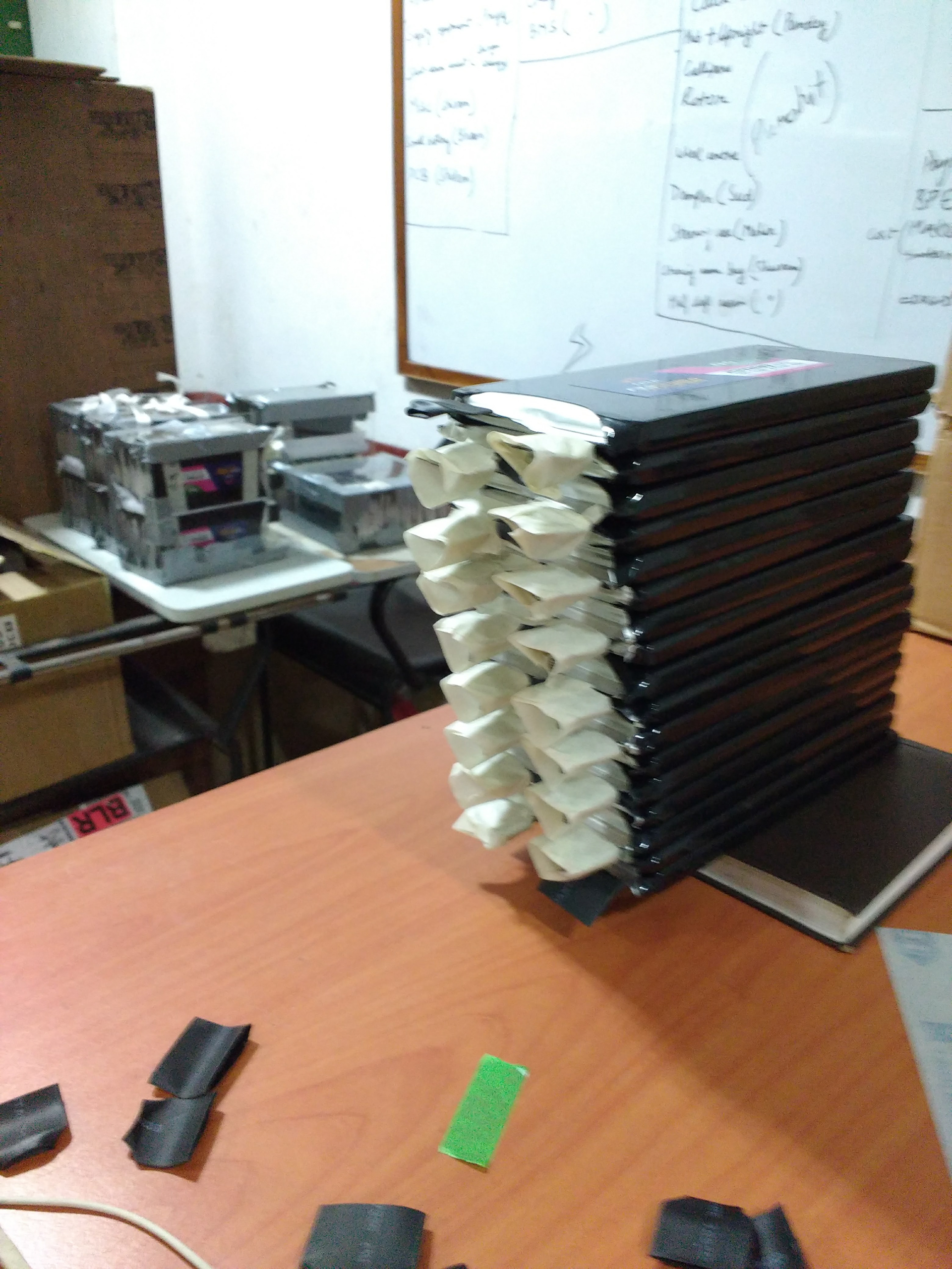
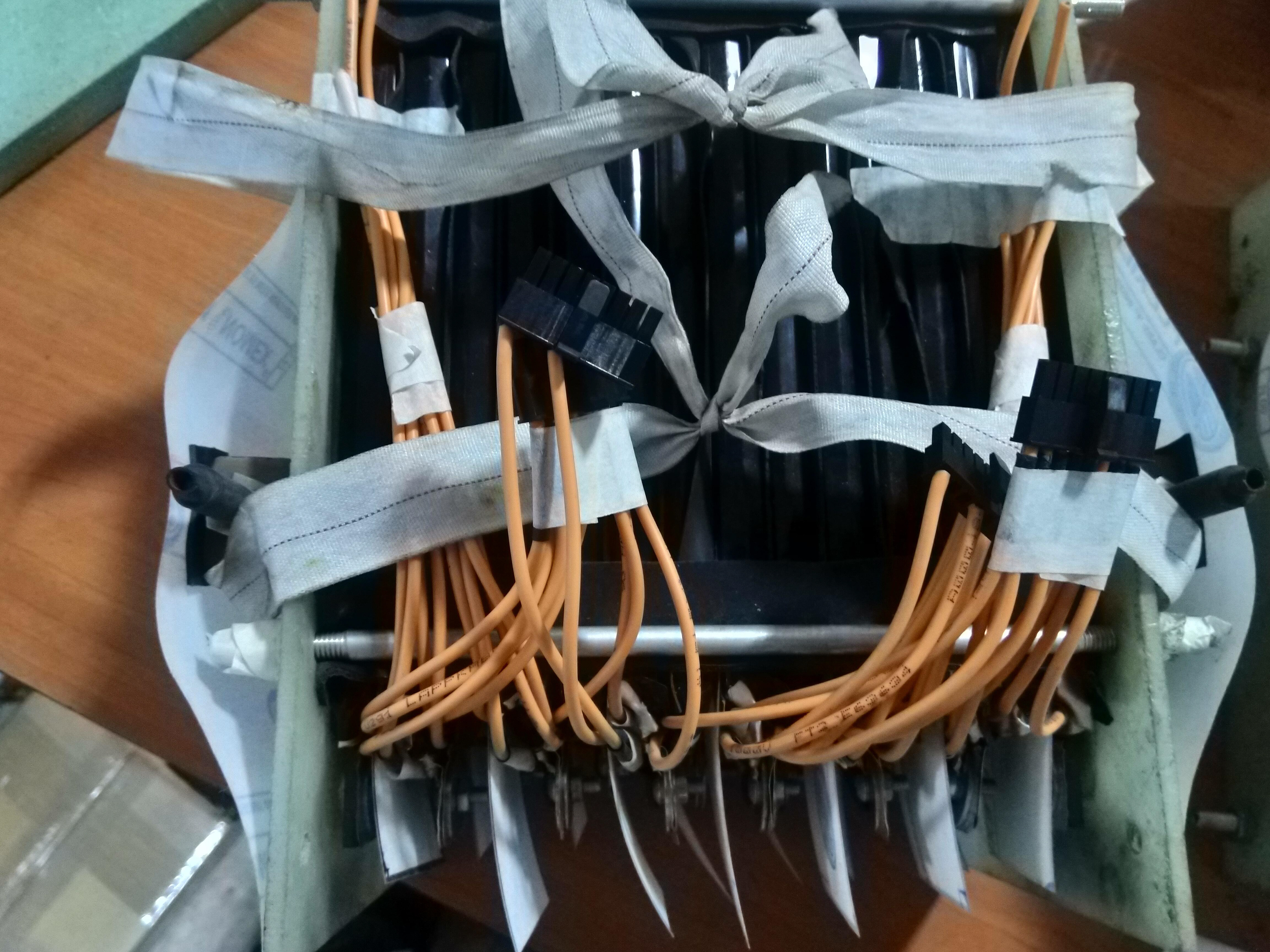
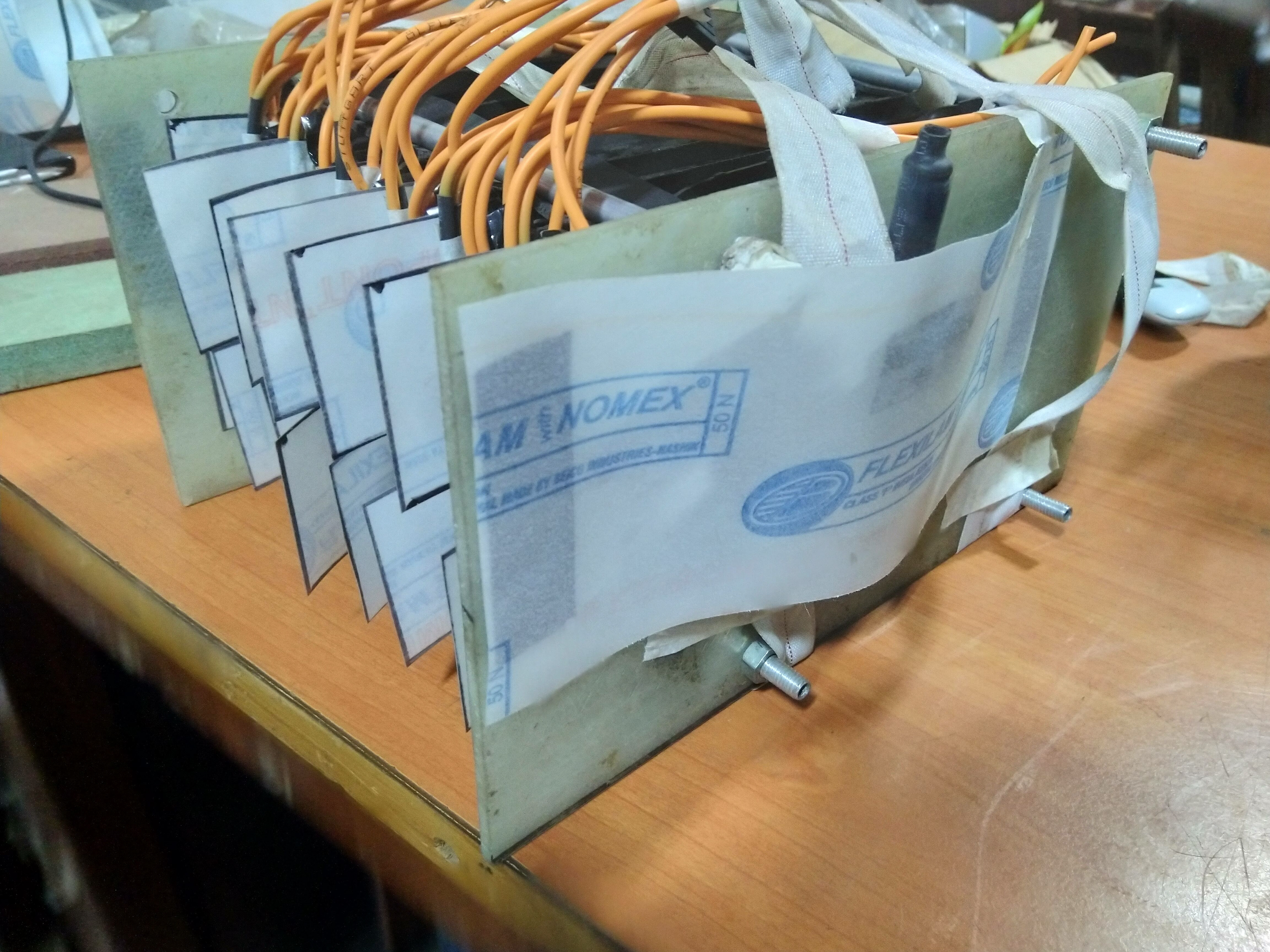
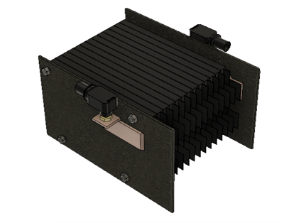
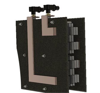
•The cells are placed next to each other and bound between two end plates made of GFRP.
•Electrical connections are made using nut and bolts to maintain tight contact.
•Compressible rubber sheets are placed between all surfaces to allow for expansion of cells during use.
•End plates are held together using Aluminium rods fastened using nuts.
•Bus bars are used to get the cell terminals to an accessible location.
•All stacks are terminated using Amphenol Radlok pins.
Overall internal packaging
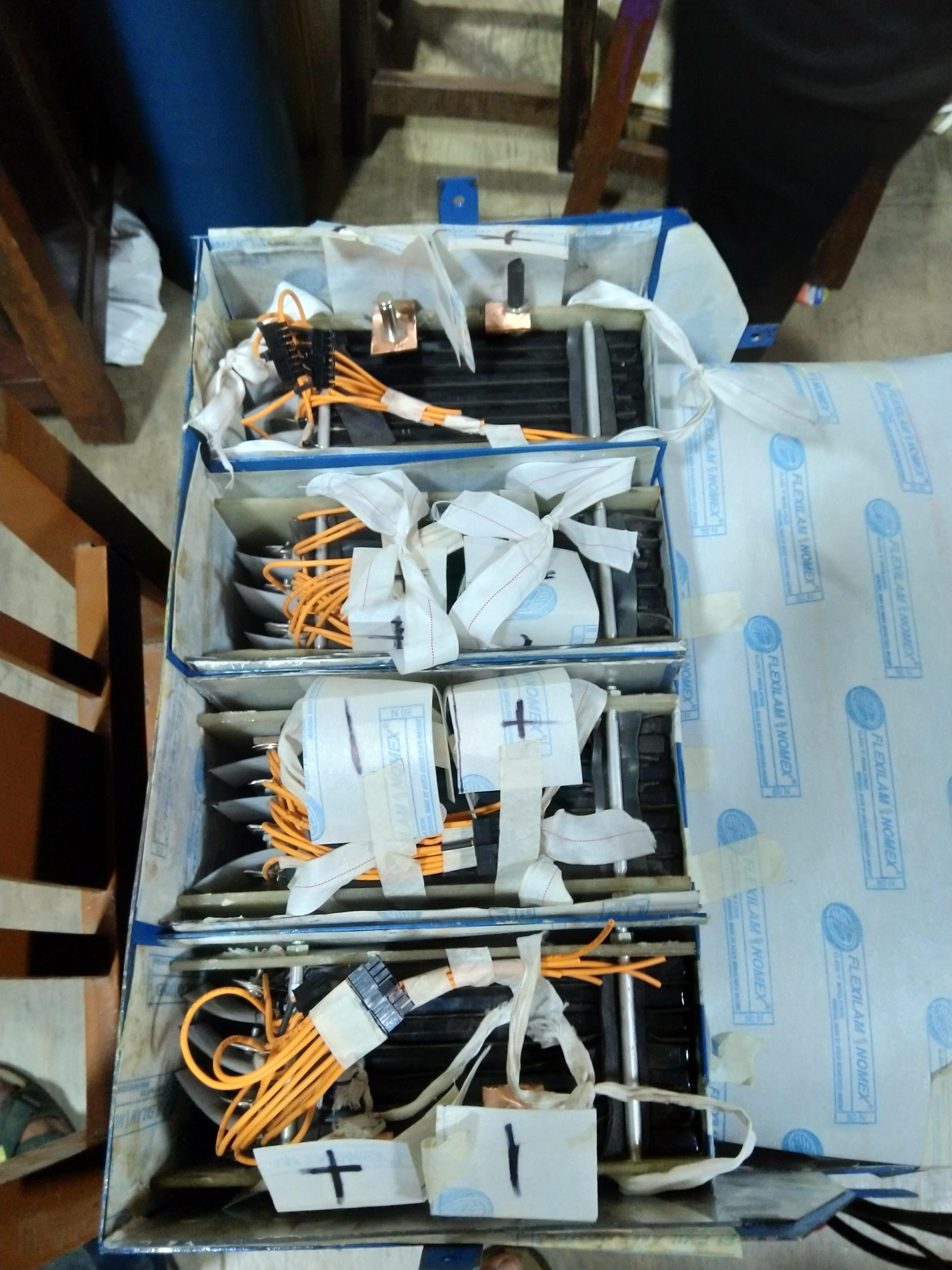
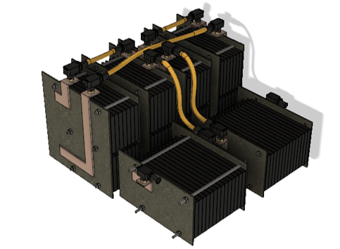
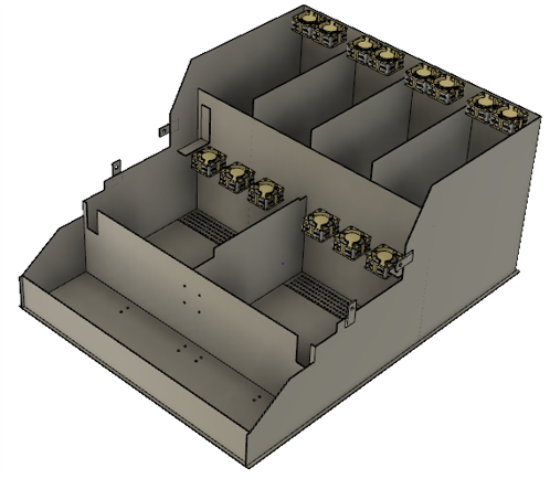
4 stacks with two layers of cells, 2 segments with a single layer. This allows the container to sit right under the driver’s back.
All terminals have been placed so that there is no overlapping of high current wires.
Container
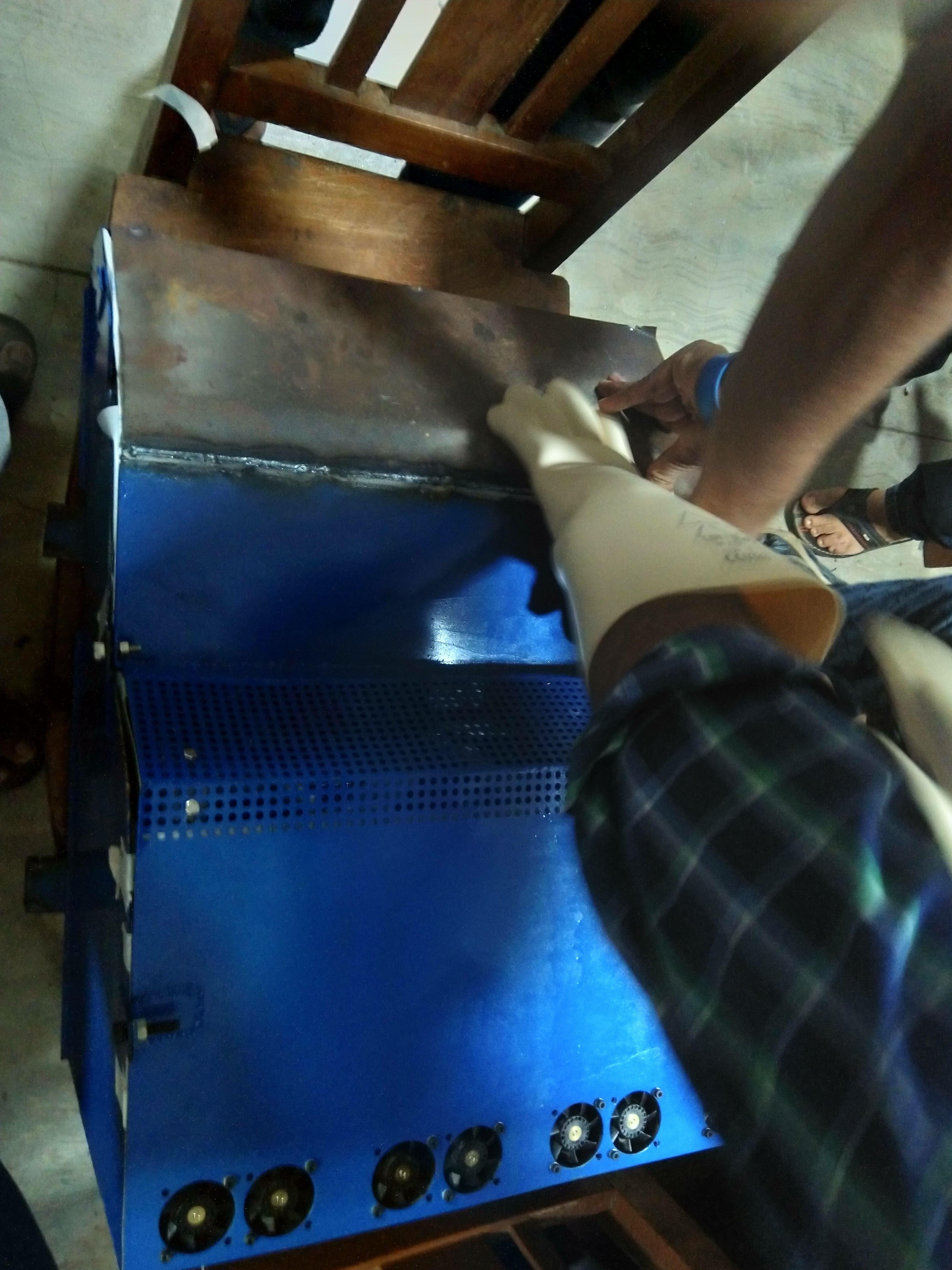
All vertical walls of the accumulator container will be made of 1.5mm thick stainless steel, while the base plate will be 2 mm in thickness.
All joints will be made by welding the sheets together for a better seal.
Thermal Management
Goals of accumulator cooling:
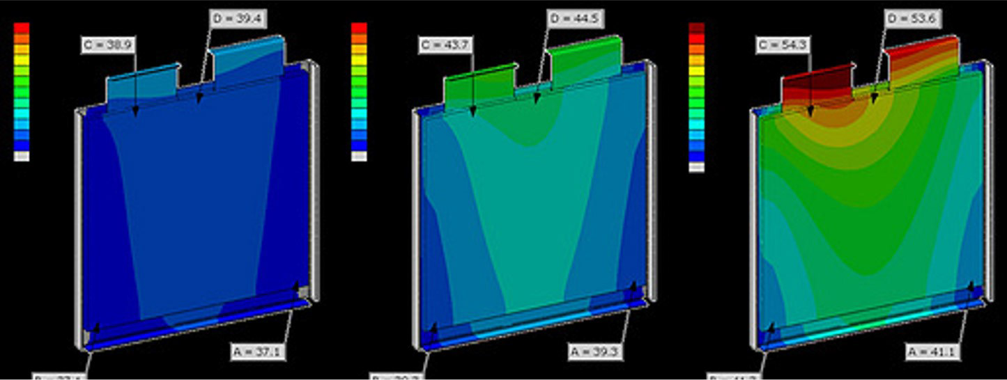
•Not to reach cell’s max temperature i.e. 50 degrees Centigrade.
•To make it simple, safer and reliable.
•Minimize openings on the container for fire safety purposes.
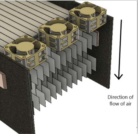
Forced air convection using fans was the chosen cooling method as it was safer than liquid cooling and more efficient when compared to natural convection. It was found that cooling the tabs at moderate discharge rates would be sufficient for our purposes.
Fans were placed on top of the tabs directly to create turbulent flow of air which is desirable for heat transfer. Holes were placed on top and bottom of the container to allow for a through passage of air.
Thermal Design with Karan Kumar, Priyaj Mehta
Assembly and Test
